Metex Ms 9150 Manuals
Feb 28, 2018 - If searched for the ebook Ms 9150 service manual in pdf form, then you've come to the faithful site. We presented the complete variant of this.
Schematics 4 Free Service manuals, schematics, documentation, programs, electronics, hobby.
Nov 02, 2010 Thrustmaster HOTAS Warthog Serial. Only DCS World keys purchased from these locations are valid purchases and can be activated in the Module Manager: DCS E. A 10c Warthog PC keygen Crack discussion We want to help the girl.  Warthog brings the most realistic PC simulation of a modern 'DCS: A-10C Warthog' is a PC simulation of the U.S. Premier Close Air Support attack aircraft. This is the second aircraft in the DCS series, following DCS: Black Shark, and raises the bar even higher in the DCS series.
F) OFFSET adjustment - The DC voltage level of the output signal can be adjusted with the OFFSET control knob in the range of +/- 10 V. - To set the DC voltage level, pull this control knob out. Turning to the right means positive voltage, turning to the left means negative voltage. - If the control knob is pressed, the output voltage will have no DC voltage component. G) Symmetry adjustment - The symmetry of the output voltage can be changed in the range of 1:3 and 3:1. The control knob carries the designation SYM.
- To change the symmetry of the waveforms, pull the SYM control knob and turn it slowly to the left (ccw) or to the right (cw). Refer to the table for the resulting waveforms. BASIC WAVEFORMS CLOCK WISE (CW) COUNTER CLOCKWISE (CCW) SINE SKEWED SINE SKEWED SINE SQUARE PULSE PULSE TRIANGLE SAWTOOTH SAWTOOTH Note!
Note that because of this adjustment of symmetry, the frequency can change and therefore should be readjusted. H) SWEEP adjustment (Wobbler) - To operate the built-infrequency sweep, pull the SWEEP WIDTH control knob and use it to adjust the width of the sweep signals in the range 100: 1. - To achieve maximum width, turn the frequency adjustment knob (with scale) to its left stop and the width control to its right stop. - To adjust the speed of the sweep signal, turn the SWEEP RATE control knob slowly to the left or right. A linear sweep signal is obtained. - A logarithmic sweep signal is possible by pulling the SWEEP RATE control knob.
I) TTL output - The TTL level is available at the TTL OUT socket (BNC). A TTL level is an 'asymmetric square wave'. It is asymmetrical because, in contrast to the sine or 'pure' square waves, the signal does not cross zero, i.e. It has no negative voltage values (negative logic excepted).
- The TTL output can drive 20 'unit loads' when HIGH and 15 'unit loads' when LOW. - One 'unit load' is 40 µA for the HIGH and 1.6 mA for the LOW state.
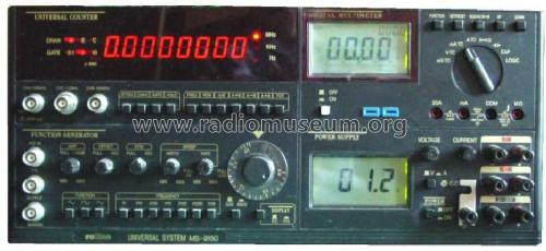
J) Output impedance - The output impedance of the generator output F/G OUT, is 50 Ohm or 600 Ohm depending on the setting of the 50 / 600 Ohm switch. 5.3 The DC voltage measuring instrument Operating elements 1. Illuminated 3 1/2-position 5. Adjustable current limiting 17 mm high LCD display 6. Ground connector 2.
Voltage adjustment 7. Fixed voltage output 5 V / 2 A 3. V/A display switch 8. Fixed voltage output 15 V / 1 A 4. AC power main switch 9.
The characters from the last game Captain MacTavish and Captain Price return to the scene from Modern Warfare 2 and there and some new playable characters that have been introduced. The story is told with perspective from different characters happening at the same time at different locations in the world. Download only file setup exe cod mw3 reloaded free. You have enough time to enjoy the surroundings but not enough to languish. The game sends you in an all out war and all missions are so intense you don’t have any time to relax.
Adjustable output 0-30V / 0-3A Attention! Safety measures! Protect the instrument from being dropped and from external mechanical damage by falling objects. Do not short circuit the '+' and '-'terminals. Never go beneath the maximum permitted load of 2.5 Ohm at the 5V/2A output and 15 Ohm at the 15V/1A output. Basic settings a) Before connecting the AC power cable, ensure that no load is present on the output terminals of the power supply. B) Centralise the (CURRENT) current-limitingcontrol knob.

C) Switch the AC power switch (POWER) on. D) The LEDs under the legends 5 V and 15 V light up. E) Connect the loads to the 5V and 15V output.